7 Quality Parts of Marine Engine Crankshaft
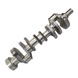
The components of the Marine Engine Crankshaft and schematic diagrams:
- Crank pin
- Major journals
- Crank net
- Counterweight
- Thrust washer
- Oil passages and oil seals
- Flywheel mounting flange
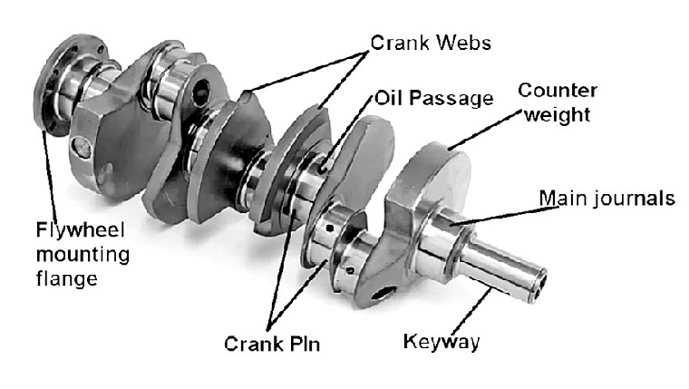
1. Crankpin
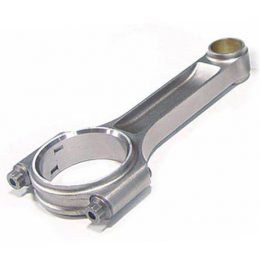
The crankpin is a mechanical part of the engine. This allows the connecting rod to be attached very firmly to the crankshaft.
The surface of the crankpin is cylindrical to transmit rotational force to the big end of the connecting rod. These are also called connecting rod journals.
2. Main journals
Main bearing journals, or just main journals, are clamped in the engine block, and the engine rotates around these journals. All crankshaft journals will be machined very smooth and round and often hardened. The main journal is fixed in the saddle, where the replaceable bearing insert will be located. Bearings are softer than journals, can be replaced when worn, and are designed to absorb small amounts of contaminants (if any) before they can damage the crankshaft. The main bearing cap is then bolted to the journal and torqued to exact torque specifications.
The journals run on an oil film that enters the space between the journal and the bearing through holes in the crankshaft saddle and corresponding holes in the bearing insert. With the correct oil pressure and oil supply, the journal and bearing should not touch.
3. Crank net
The crank web is the most important part of the crankshaft. The crank web connects the crankshaft to the main bearing journal.
4. Counterweight
The counterweight is the most important component of the crankshaft. These contribute to the smooth running of the crankshaft. When the piston reaches top dead center, the side with the heavier weight reaches its lowest point.
When the piston reaches the bottom dead center, the heavier side reaches its highest point. This results in smooth operation due to potential energy changes created by the counterweight.
5. Thrust washer
At some point, it provided two or more thrust washers to stop the crankshaft from moving longitudinally. It assembled these thrust washers between the web and the machined surface of the crankshaft saddle.
With the help of thrust washers, clearance is easily maintained and helps reduce lateral crankshaft movement. In many engines, these are manufactured as part of the main bearing. Usually, older types use separate washers.
6. Oil circuit and oil seal
The crankshaft oil gallery transfers oil from the main bearing journal to the big end journal. Drill holes are usually drilled in the crank web. When the crankpin is in the up position and the combustion force pushes the connecting rod to the down position, it allows oil to enter between the journal and the bearing.
The crankshaft has some extension beyond the crankcase at both ends. This can cause oil to leak from these ends. Therefore, in order to prevent oil from flowing out of these openings, oil seals are provided. Front and rear connections have two main oil seals.
1. Front-end oil seals: They are very similar to the rear-end oil seals. However, its failures are less disruptive and more accessible. The front oil seal will be set behind the pulley and timing gear.
2. Rear end oil seals: it placed them inside the main journal and flywheel. This is pushed into the hole between the engine block and the oil pan. The oil seal has a molded lip that is held tightly in the crankshaft by a spring called a snap spring.
7. Flywheel mounting flange
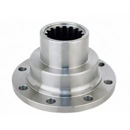
As the name suggests, means of a flywheel flange attach the vehicle’s flywheel to the crankshaft. The flywheel flange is attached to one end of the crankshaft.
It is designed to hold the flywheel securely. This is because the flywheel is a heavy mechanical device that spins at a very high speed.
