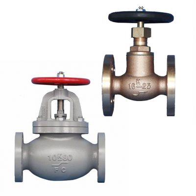
Marine Globe Valve
Marine Globe Valve
Marine Globe valves are some of the most versatile valves in marine applications. They derive their name from their round, globular body. Globe valves are great at modulating, or “throttling”, flow because of their internal makeup. In a globe valve, water or another medium travels in the bottom inlet of the valve passes up past the seat, and out of the outlet. To stop the flow, a disc is lowered onto the seat in the middle of that S shape. However, this s-shaped configuration creates a large amount of resistance within the valve.
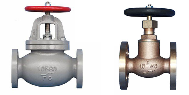
The design of the marine globe valve body forces the flow of the commodity to change direction within the valve itself. This change in direction creates substantial pressure drop and turbulence. The globe valve is therefore not recommended when flow resistance and pressure drop are to be avoided. In most installations, the commodity is routed into the valve’s body from below the valve seat and disc. This flow direction uses the pressure of the commodity to aid in the opening operation of the valve. It also reduces wear on the valve seats and disc.
Marine Globe Valve Product Range
- Design: JIS, DIN, API, GB
- End Connection: BW, RF, RTJ, UNION
- Size: 1-1/2”~48”, DN40~DN1200, 40A~1200A
- Pressure: JIS 1K~63K, 125LB~2500LB, PN10~PN420
- Material: Cast Iron, Stainless Steel, Bronze
- Operator: H.W., Gear, Pneumatic Actuator, Electric Actuator
Applications of Marine Globe Valve
Marine Globe valve can be used in a wide range of services; both low pressure and high-pressure fluid services. The typical applications of globe valves are:
- Cooling water systems require flow regulation.
- Fuel oil system requiring leak-tightness.
- Control valve bypass systems.
- High-point vents and low-point drains.
- Oil and gas, feedwater, chemical feed, refinery, condenser air extraction, and extraction drain systems.
- Boiler vents and drains, steam services, main steam vents and drains, and heater drains.
- Turbine seals and drains.
Working Principle of Globe Valve
Marine globe valve is comprised of a movable disk and a stationary ring seat in a spherical body. The seat of a globe valve is in the middle of and parallel to the pipe, and the opening in the seat is closed off with the disk. When the handwheel is rotated manually or by an actuator, the disc movement is controlled (lowered or raised) by the valve stem. When the globe valve disc seats over the seat ring, the flow is completely stopped.
But when the disk is lifted the flow begins as the upward movement of the disc creates space for the fluid.
3 Types of Marine Globe Valve
- Standard Pattern (also known as Tee Pattern or T–Pattern or Z–Pattern)Globe valves possess the lowest flow coefficient and a higher pressure drop. In severe throttling services, such globe valves can be used. If the pressure drop is not a concern and throttling is required, the Tee type globe valve will be a good choice.
- Wye Pattern(Y-Type) Globe valves can be cracked open for long periods without severe erosion. They offer very low resistance to flow. For start-up operations, Y-type globe valves are extensively used.
- Angle Pattern Globe valves turn the fluid flow in a perpendicular direction without the use of an elbow. For pulsating flow services, angle-type globe valves are used because of their capability of handling the slugging effect.
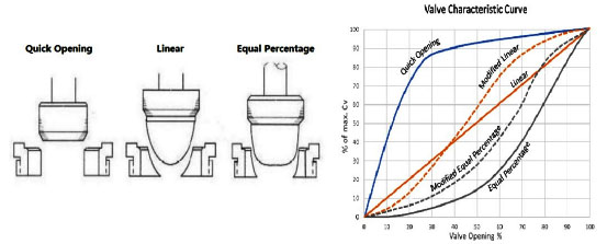
Marine Globe Valve Characteristics
- Quick opening
- Linear
- Equal percentage
Main Parts of marine globe valve
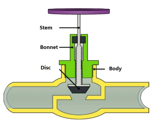
Body:
The body of the valve contains all the main internal parts, forming the mass of the valve. It has ports that allow the flow of the fluid or gas in or out of the valve. The globe valve typically has two ports. The ports can be in a straight line or at an angle. The shape of the body determines the type of the valve. Globe valve manufacturers in India make three types of valves — tee pattern, angle, and Wye pattern. These are explained in detail below.
Stem:
The stem connects the actuator to the valve inside. Its main function is to transmit the actuation force. Actuator-controlled valves or automatic vales have smooth stems surrounded by packing material. The packing material prevents leaking and has to be replaced during maintenance. Manual valves have threaded stems.
Disk:
The disk forms the closure system of the valve. Connected to the stem, the disks move up or down to control the flow. Plugs are either balanced or unbalanced. Unbalanced plugs have a simple design that is used in case of low-pressure drops. Balanced plugs have holes. These are easy to shut off.
